
External Speed / RPM
External Speed.
The best is to have the controller setup to EXTERNAL SPEED SENSOR.
But as many of the old cars do not have any, the controller can work with the speed sensors internal in the gearbox.
The reason is that the 722.6 do NOT has an speed sensor on the output shaft !
It has two RPM sensors on 2 different rotating parts in the gearbox, yes i can use them to calculate the speed of the car.
But as it is not possible to calculate speed while a shift is going on, the controller can make wrong speed if a shift is not happening as expected.
This is why i suggest you connect an external speed sensor,
"Setup Parameters" -> "Speed INT/EXT" (to deside if you are going to use External speed sensor or not 0=External 1=Internal )
Or
"Setup Parameters" -> "RPM INT/EXT" (to deside if you are going to use External RPM sensor or not 0=External 1=Internal )
PUT “W/S” in W position
1.Power up, but do NOT start engine.
2.Press Joystick down to “Setup Parameters”
3.Press Joystick Right, to enter this menu
4.Now you are in SETUP MENU.
5.Press Joystick down until "Speed INT/EXT"
6.Press Joystick Right, to enter this menu
7.Press Joystick up and down to set it to 0 or 1
0 You need External Speed
1 Internal speed from gearbox is used
8.Press Joystick Right to save
9. PUT W/S in S position, and do point 1-8 again.
An external speed sensor is absolutely to prefer, as there is some limitation on the internal speed, as the speed can not be read while shifting.
After connected the External speed sensor, run the car slow 10 km/h and see what the speed says, in “LiveData” if it is not correct adjust in setup menu
"Setup Parameters" -> "Ext Speed %"
SpeedoMeter
Great Link to keep speedo working on old cars from here
FROM the link
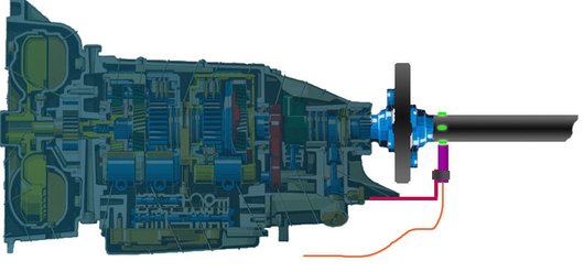
But I figured out how to move the internal VR trigger wheel to the driveshaft and keep the tailcone with the manual speedo on the 722.4. Here's a diagram of the strategy. (The full thread on this topic, including images of the proof-of-concept test is here - Mechanical to Electronic Speedometer Conversion )
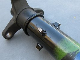
Essentially the driveshaft is turned into a trigger wheel by permanently affixing properly shaped and balanced "teeth" to the end nearest the transmission. An excellent mounting point for the sensor bracket is the rear transmission mount. Everything else remains stock. In the graphic above, the purple is the stock sensor, the green are the "teeth" and the red is the custom mounting bracket.
This strategy will likely be a good solution for others doing manual transmission conversions in cars with electronic speedometers.
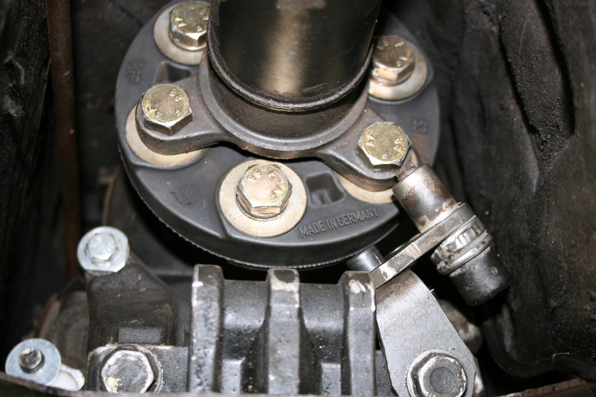
This is one way of adding an Reluctance Sensor, it can be an RPM sensor from almost any old Mercedes engine.
This sensor just need Ground and connect it to the Controller Speed input.
The sensor works this way, There is a magnet in the sensor, that means that it gives voltages if just a piece of metal flyes by.

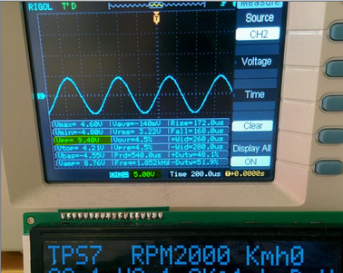
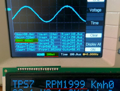
Here some Picture from testing the Variable−Reluctance Sensor Interface, in the Controller.
It works as it should, tested +/- 0.2 Volt to +/- 10 Volt, but it accept mutch higher volt on the input.
But it need to cross 0V to work, that means it would not accept 0-5 volt squre signal from a hall sensor.
On the Display i am testing on the RPM input, but External RPM and Km/h input are the same.
Now running External speed from the ABS sensor on my own car, works perfect,
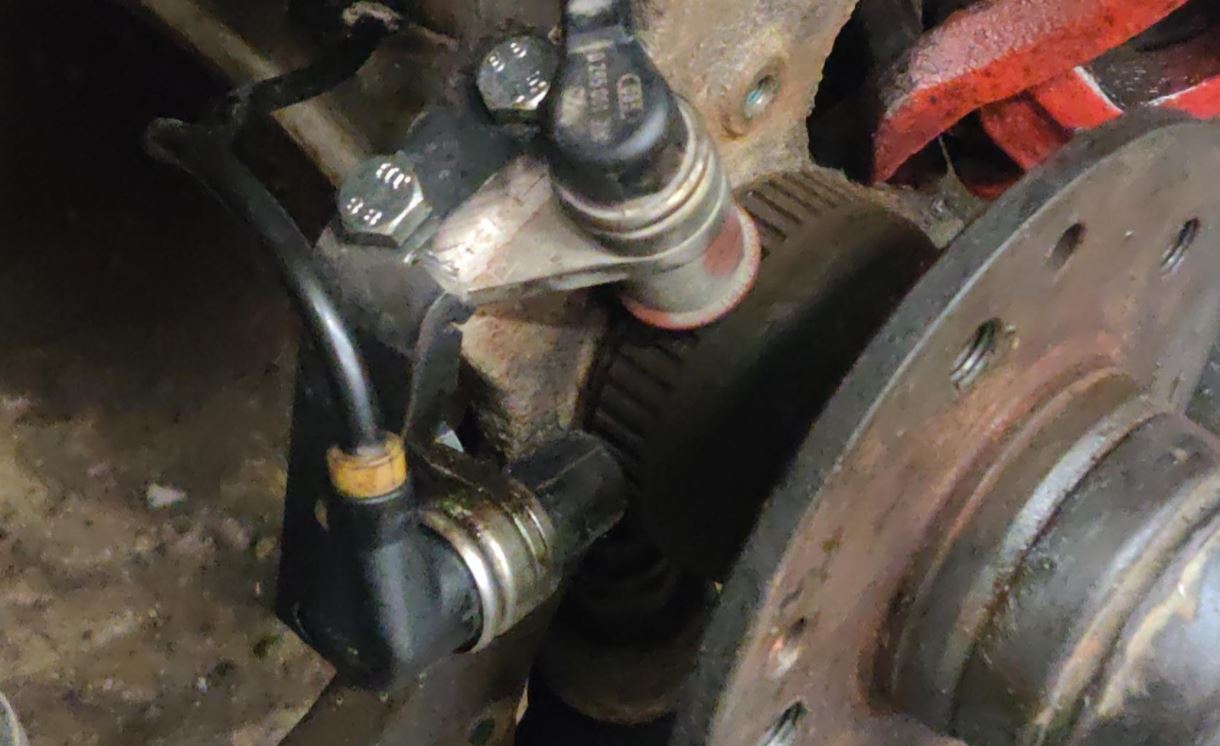
Here i use an RPM sensor
0281002123
Can be found used on any old Mercdes engine
W201 sensor should work
But W202 seems to be different i have heart, and not working.
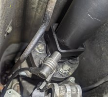
On the picture to the right an W201 sensor has been mounted to the hub
Also from HW5 and up
And Software 181 and up
It is possible to make the input less sensetiv by set the
"Setup Parametera" ->
“Speed EXT/INT” set it to 0 = +/- 0.5V
“Speed EXT/INT” set it to -1 = +/- 1.0V
Default the external speed input trigger
(HW4) look down left on label on the controller
is set to +/- 0,2 V
(HW5 & HW6)
is set to +/- 0,5 V / 0-0,5V (inductiv or hall sensor)
That means that the signal from an ABS sensor has to be bigger then 0.2V to trigger.
But if you know what you are doing and want to change that is is possible.
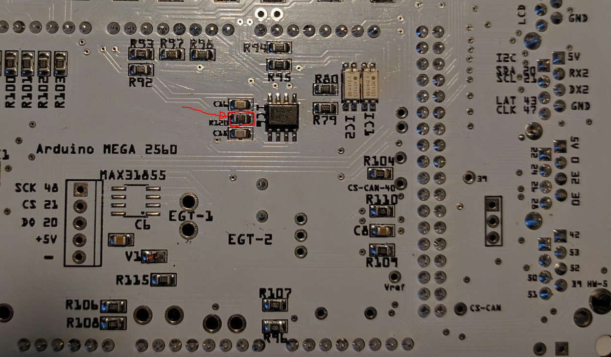
If you want to change change resistor to see below
+/- 0,5 V
The resistor on the picture has to be arounfd 50K Ohm
+/- 1V
The resistor on the picture has to be arounfd 100K Ohm
Click the picture to see in bigger Size
W463 External speed
If the signal is taken from the Cruse control output, it is a squre signal, that is not acceptet by my controller as it is an ABS sensor chip,
The way to get it to work is do a little circuit like below.
2 x 1000 Ohm resistors
1 X 100 NF Condensator
Connect it like the circuit below, and then it works, has been tested on my own car.

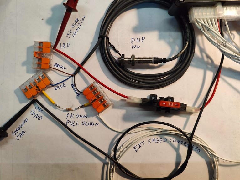
External speed sensor Hall tybe
This sensor is the tybe that has power all the time 12V connected to same place as Controller.
And Ground Connected to same plase as Controller
Then the signal wire that then gives 0-12-0-12-0-12 Volt, goes to the White wire on controller "EXT Speed"
Controller setting need to be set to EXT speed to be active.
Also an "Pull Down" resistor need to be mounted between GROUND and SIGNAL this is to make sure that the voltage is 0 also when there is noise from other electronic in the car
Copyright © All Rights Reserved